Simplicity Studio V5
Silicon Labs Tools Overview
Silicon Labs provides several tools for EFR32 development. See the full list.
| Tool | Description |
|---|---|
| Simplicity Studio | Full IDE with GUI for project creation, configuration, and flashing |
| slc | Command-line tool to create and configure projects |
| Commander | Flash, debug, and secure devices via GUI or CLI |
| Network Analyzer | Capture and analyze wireless network traffic |
Simplicity Studio V5 is Silicon Labs' official IDE for developing and flashing firmware onto EFR32MG1B chips. It is an alternative to the CLI-based approach used in this project (see 24-NCP-UART-HW, 25-RCP-UART-HW, etc.) which uses slc.
Note: The EFR32MG1B is a Series 1 chip. Simplicity Studio V5 is the latest Silabs IDE supporting Series 1. The newer Simplicity Studio V6 only supports Series 2 chips.
Download
Download from the official Silicon Labs website:
https://www.silabs.com/software-and-tools/simplicity-studio/simplicity-studio-version-5
A free Silicon Labs account may be required later to download SDKs.
Notes
- Debugger (J-Link, etc.): Required to flash firmware via SWD. See 22-Backup-Flash-Restore for hardware setup.
- Administrator Privileges: On some Linux systems, you may need to run Simplicity Studio as root.
- udev Rules for Debugger Access: If your debugger is not recognized, create a udev rule:
- Java Dependencies: If Simplicity Studio fails to start, ensure you have Java installed:
Example 1: Building the Bootloader (UART XMODEM)
Step 1: Load the Gecko bootloader-uart-xmodem demo file
The Gecko bootloader-uart-xmodem firmware is available by default as an example
application for the EFR32MG1B232F256GM48 chip.
-
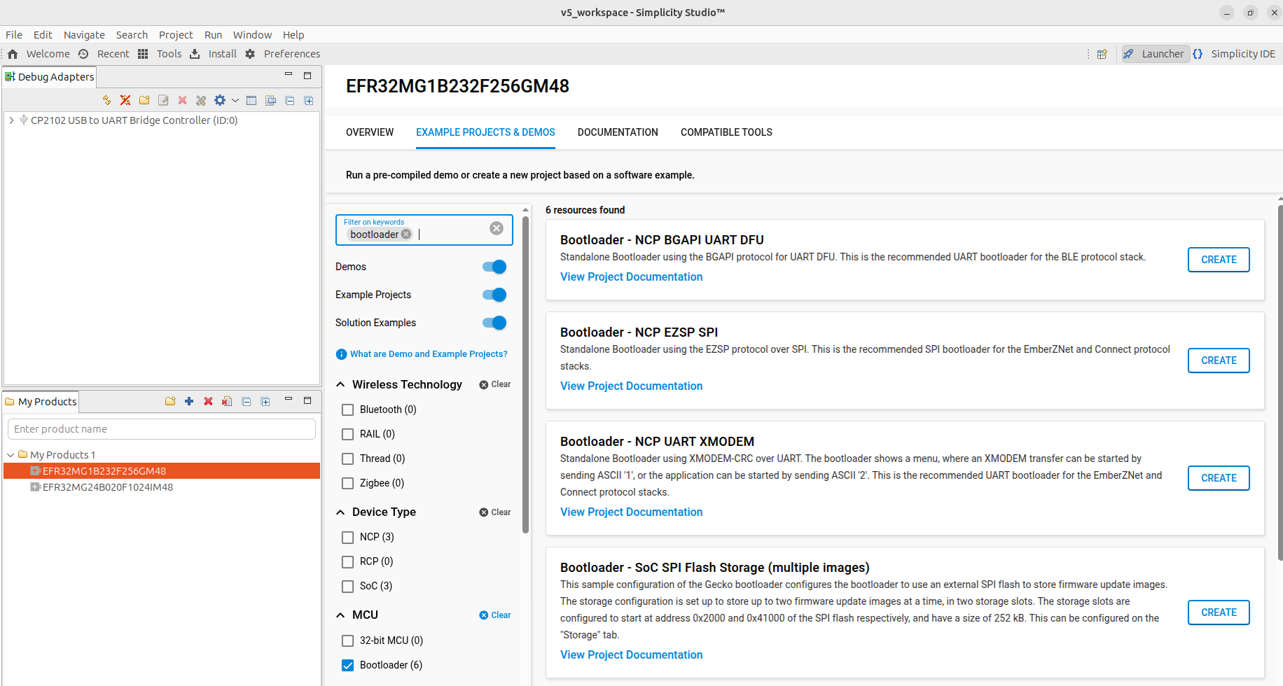
In the Launcher tab, add the
EFR32MG1B232F256GM48part to the My Products list, then click Start. -
In the Example Projects and Demos tab, search for
bootloader, choose theBootloader - NCP UART XMODEMproject and enterCREATE
-
Accept default options and click Finish. Wait until the C/C++ indexation is complete.
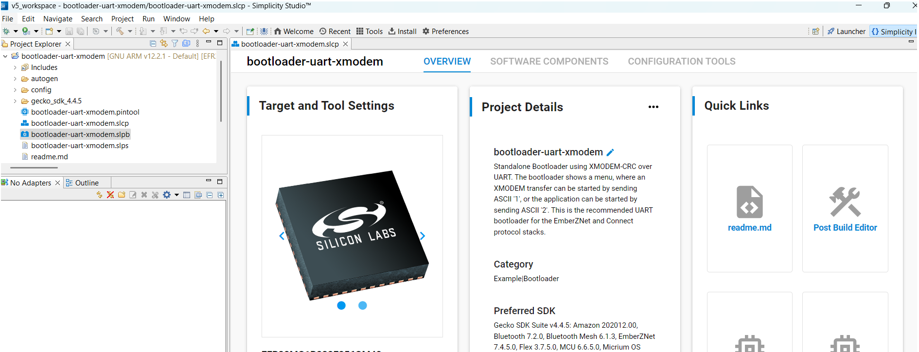
Step 2: Pin Assignment
-
In the Configuration Tools panel, open the Pin Tool.
-
Assign
PA0,PA1,PB13respectively toUSART0_TX,USART0_RXandDBG_SWVas shown below:
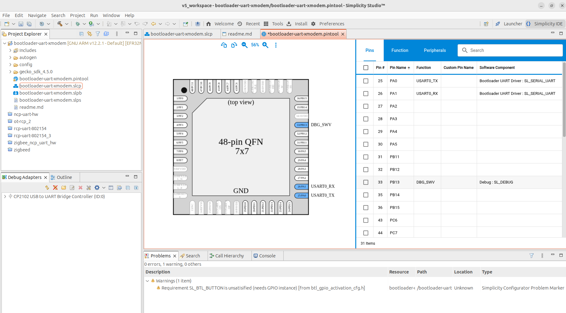
- Exit the Pin Tab and save.
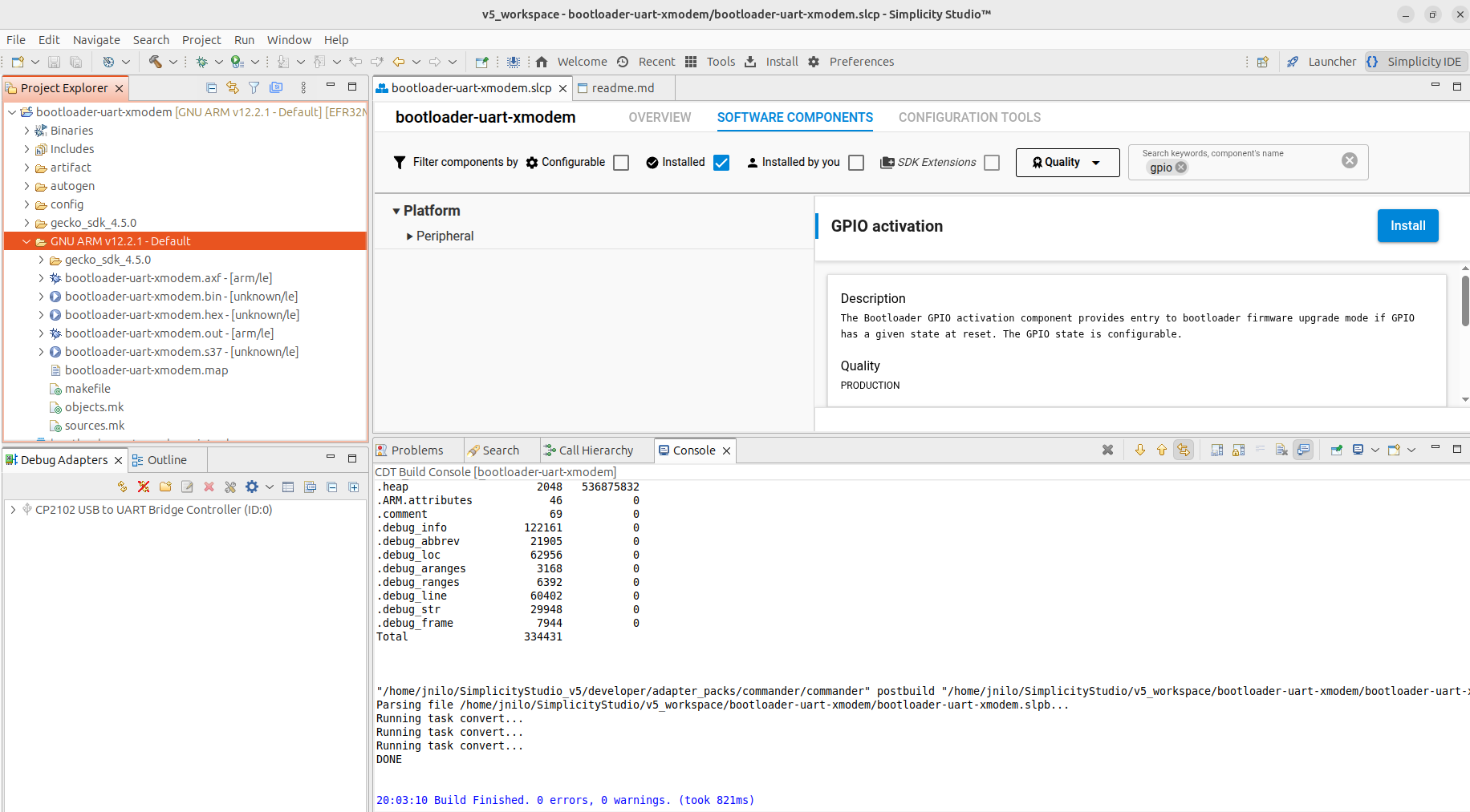
Step 3: Fix Pre-compilation Warning
We want to get rid of the SL_BTL_BUTTON warning:
-
Go back to the Project Main Panel and open the Software Components tab.
-
Set the filter to
Installed. -
Search for
GPIO.
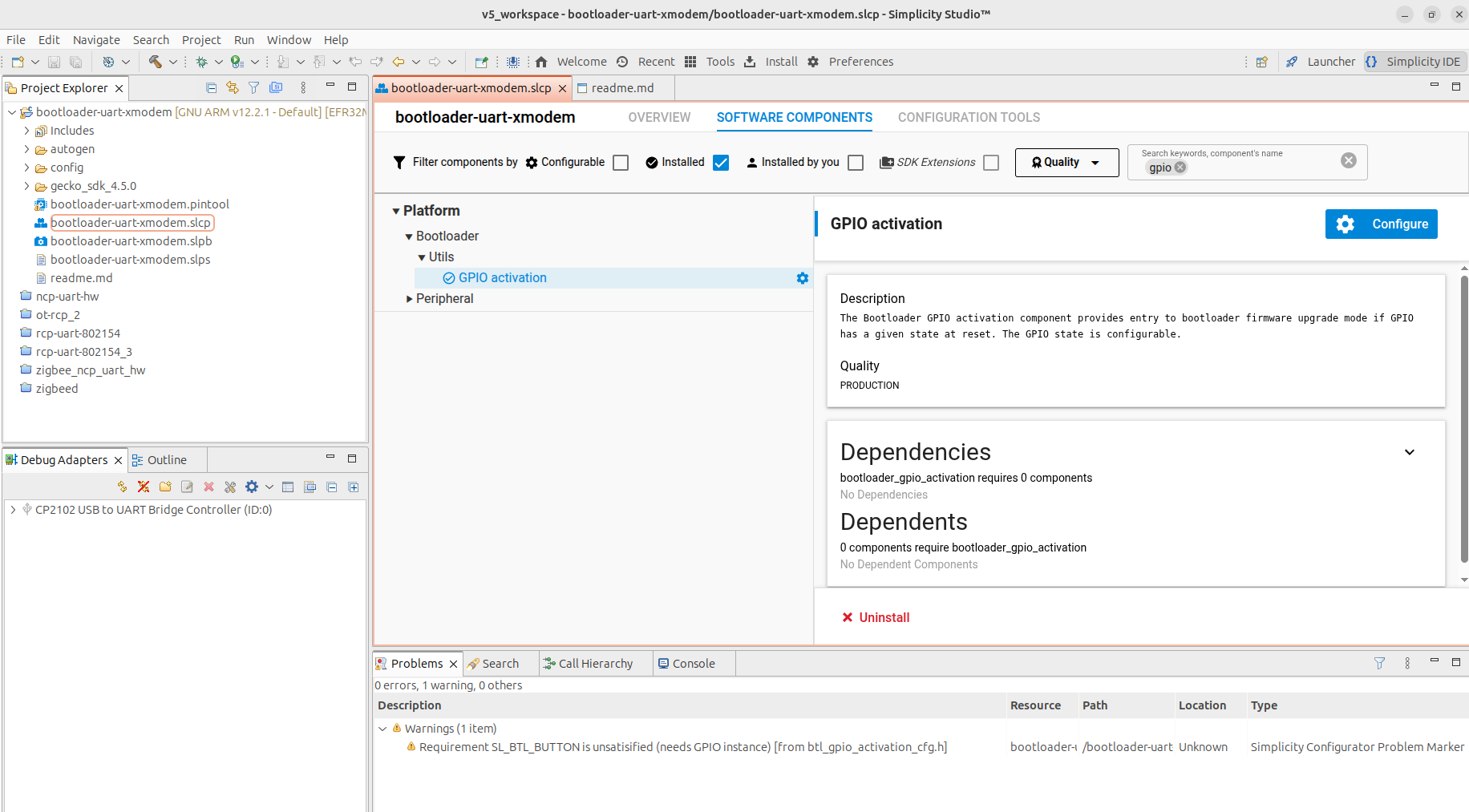
- Uninstall the GPIO activation component
At this stage, the initial pre-compilation warning should have disappeared.
Step 4: Build the firmware
Right-click on the project name (bootloader-uart-xmodem) in the
left-panel and click on Build Project. The compilation should run without
any errors. The generated files are located in the
GNU ARM v12.2.1/ directory ready to be flashed with commander.
Example 2: Building NCP-UART-HW
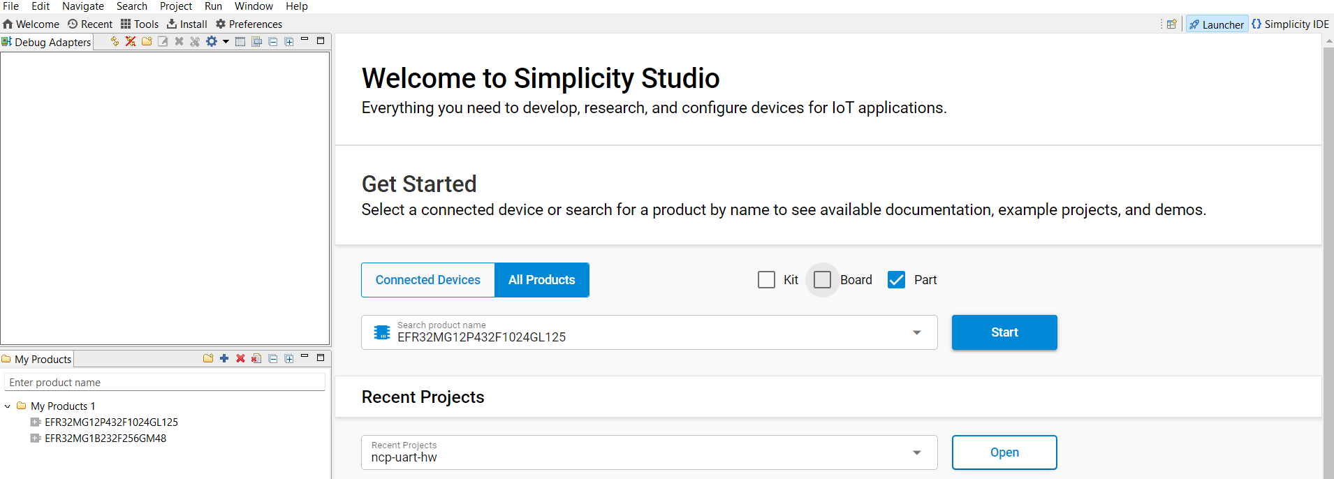
Step 1: Create an NCP-UART-HW Demo File
The NCP-UART-HW firmware is not available by default as an example
application for the EFR32MG1B232F256GM48 chip. Therefore, we need to load
it from another chip.
- In the Launcher tab, add the
EFR32MG12P432F1024GL125part to the My Products list, then click Start.
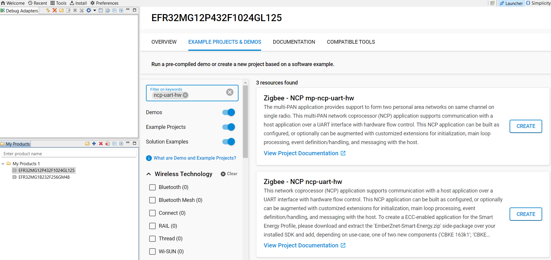
- In the Example Projects and Demos tab, search for
NCP-UART-HWand choose theZigbee – NCP ncp-uart-hwproject. EnterCREATE
-
Accept default options and click Finish. Wait until the C/C++ indexation is complete.
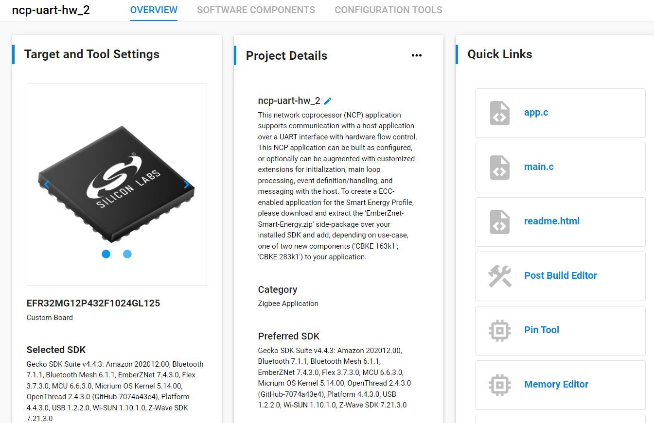
-
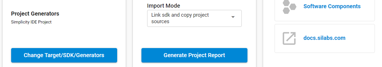
In the Overview panel, go to Target and Tools settings and at the bottom, click Change Target/SDK/Generators. Change the Part reference to
EFR32MG1B232F256GM48and save.
Step 2: Pin Assignment
-
In the Configuration Tools panel, open the Pin Tool.
-
Assign
PA0,PA1,PA4, andPA5respectively to USART0_TX, USART0_RX, USART0_RTS and USART0_CTS as shown below:
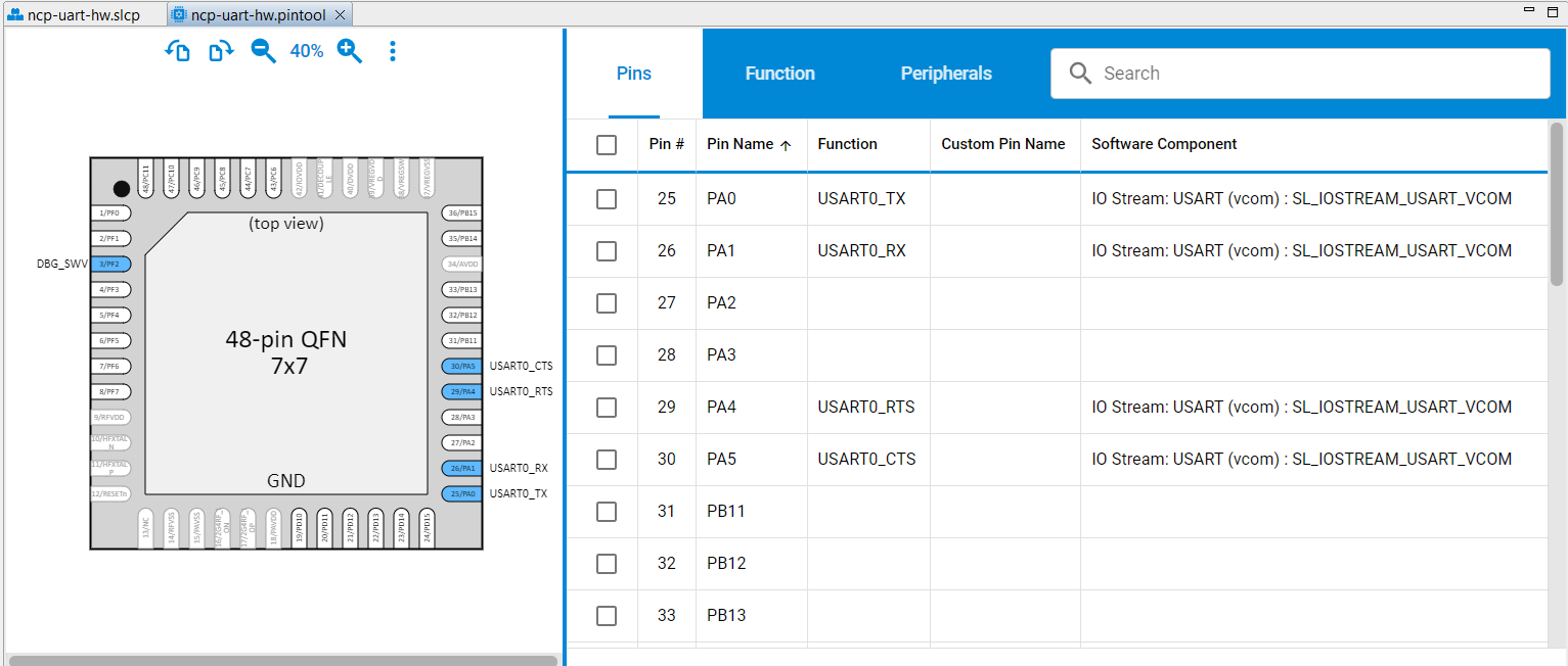
- Exit the Pin Tab and save.
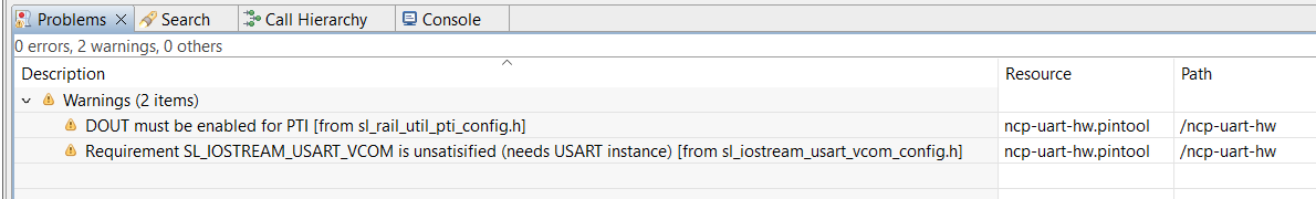
Step 3: Fix Pre-compilation Warnings
We want to get rid of the following pre-compilation warnings:
-
Go back to the Project Main Panel and open the Software Components tab.
-
Set the filter to
Installed. -
Search for
vcom.
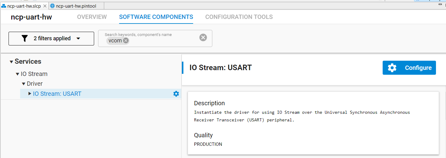
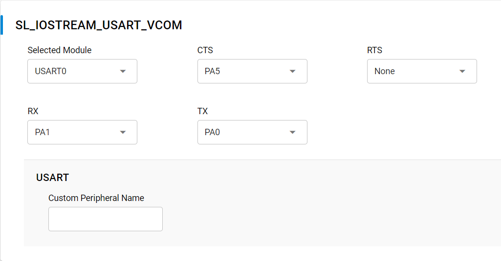
- Open the component editor for
IO Stream USARTand assignUSART0toSL_IOSTREAM_USART_VCOM.
- Search for
PTI.
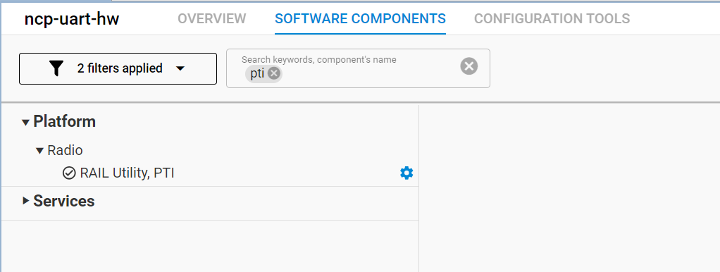
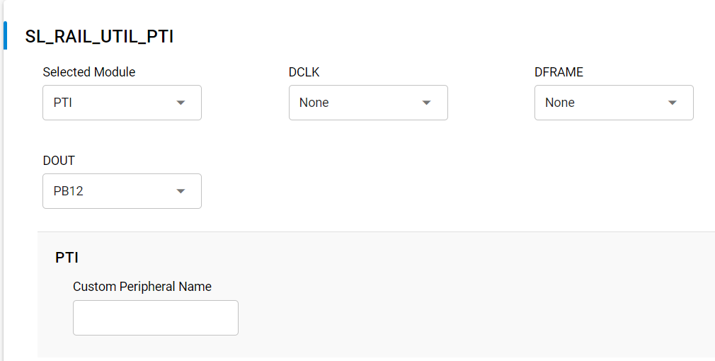
- Open the component editor for
RAIL Utility, PTIand assignPB12toDOUT.
At this stage, the initial pre-compilation warnings should have disappeared.
Step 4: Optimize for EFR32MG1B 256K Memory
If you try to compile the firmware at this stage, you will receive an error stating that the output exceeds the available memory.
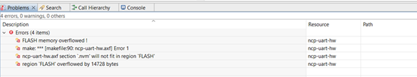
To fit within the 256K memory of the EFR32MG1B, remove unnecessary
debug or non-critical functions:
- Open the Software Components tab.
- Search for and uninstall the following components:
- Debug Print
- Debug Extended
- Zigbee Light Link
- IO Stream VUART
Ensure that the *.c indexation is completed before uninstalling the next component.
Step 5: Delay the EFR32MG1B Boot Process
The boot process must be delayed to allow the RTL8196E bootloader to
complete its initialization.
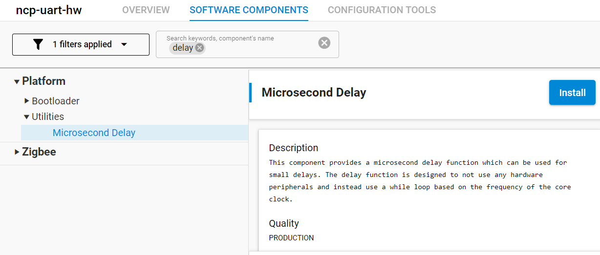
-
In the Software Components tab, search for
Microsecond Delay. -
Install the
Microsecond Delayfunction.
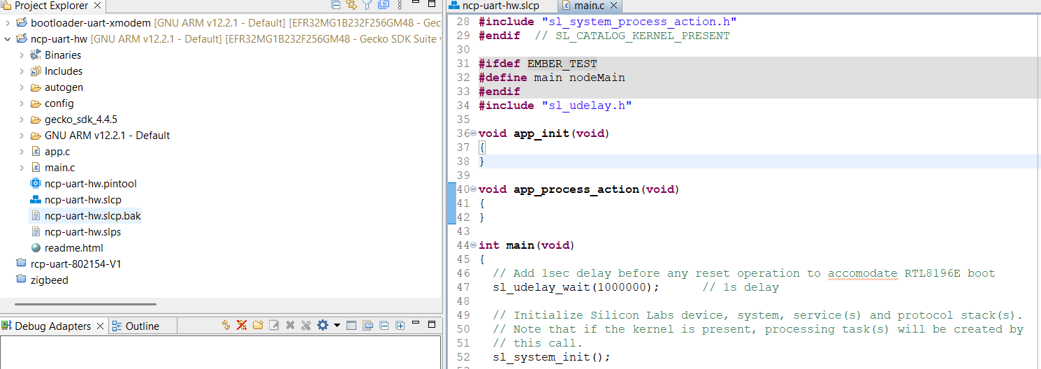
- Edit the
main.cfile and add:
- At the beginning of
int main(void), insert:
// Add 1sec delay before any reset operation to accommodate RTL8196E boot
sl_udelay_wait(1000000);     // 1s delay
The main.c file should now look like:
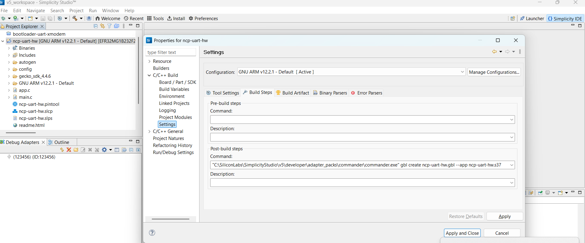
Step 6: Define post-build command to create gbl file
The ncp-uart-hw.gbl file is not created by default. Right-click on the project name and go to
Properties → C/C++ Build → Settings → Build Steps and enter:
Step 7: Build the firmware
Right-click on the project name (ncp-uart-hw) in the left-panel and click
on Build Project. The compilation should run without any errors. The
generated file ncp-uart-hw.gbl is located in the build directory ready to be flashed.