Sengled Smart Hub G4 (E39-G8C) Hardware
This page documents the Sengled G4 PCB, RTL8196E serial test pads, and the hardware differences that require Sengled-specific bootloader, kernel, and EFR32 images.
Use it together with the first-install guide,
replacing the Lidl J1 wiring with the labeled Sengled test pads below and
prefixing flash commands with BOARD=sengled-e39-g8c.
Safety and board selection
- Disconnect normal power before opening the case or moving test leads.
- Use a 3.3 V TTL UART adapter; do not use RS-232 or 5 V logic.
- Connect signal ground, TX, and RX only. Leave the PCB 3.3 V and 5 V pads disconnected and power the hub normally.
- Always set
BOARD=sengled-e39-g8c. The Lidl bootloader has different DRAM initialization and can prevent this 64 MiB board from booting.
Open the case
The screwless case is held by four plastic clips around the edge. Work around the case gradually with a non-conductive opening tool.
PCB photographs
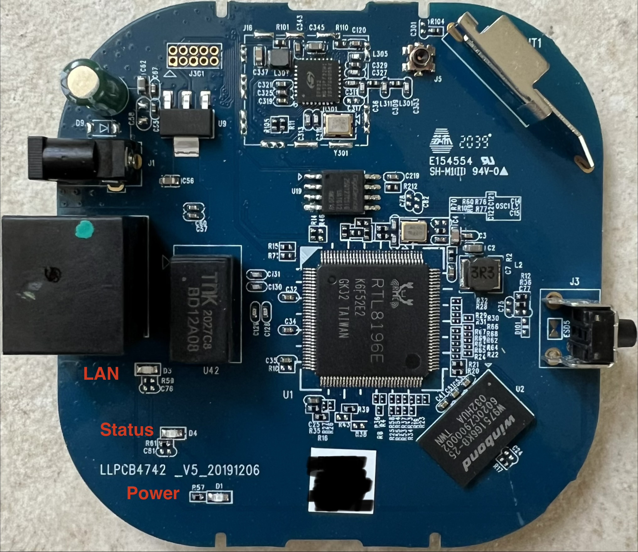
Front:
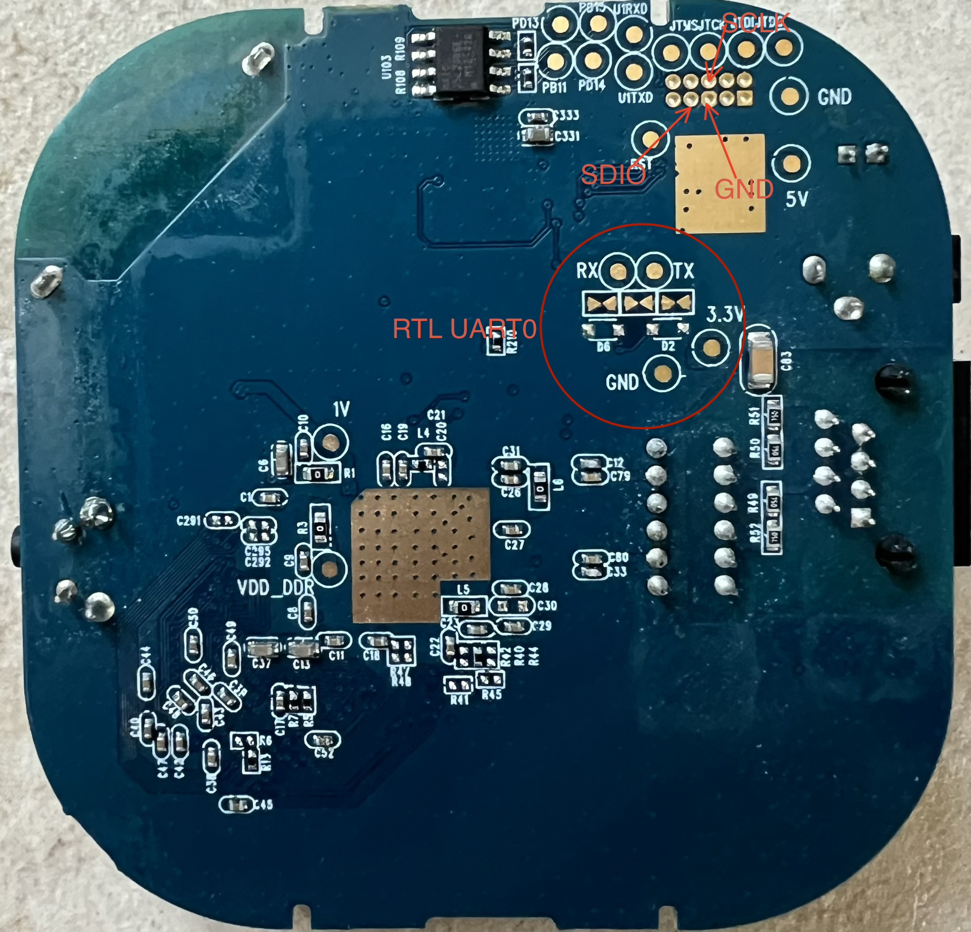
Back, including the annotated RTL UART0 area:
Connect the RTL8196E serial console
Use the group circled RTL UART0 in the back-PCB photograph. The PCB labels
the signal pads RX, TX, and GND.
| Sengled PCB | UART adapter |
|---|---|
GND |
GND |
TX |
RX |
RX |
TX |
3.3V / 5V |
Do not connect |
The console settings are:
| Setting | Value |
|---|---|
| Logic | 3.3 V TTL |
| Speed | 38400 baud |
| Data | 8N1 |
| Flow control | None |
Example:
Apply normal hub power and press Esc repeatedly until <RealTek> appears.
Then use the Sengled install command from the repository root:
Main hardware differences from Lidl
| Component | Sengled G4 | Why it matters |
|---|---|---|
| Main SoC | RTL8196E, 400 MHz | Same architecture and serial/TFTP workflow |
| RAM | 64 MiB DDR2, Winbond W9751G6KB-25 or equivalent | Requires Sengled bootloader DRAM values and devicetree |
| SPI NOR | 16 MiB GD25Q127 family | Same overall full-flash size |
| Radio | EFR32MG13P732F512IM32 | Different part and board-specific EFR32 builds |
| Radio link | UART1 without RTS/CTS | Uses software/no flow control and lower RCP/OT-RCP defaults |
| Extra radio flash | 256 KiB MX25L2006E | Board-specific radio hardware |
Components
RTL8196E main processor (U1)
- 32-bit Lexra RLX4181 core
- 400 MHz
- integrated Ethernet switch
- two 16550A-compatible UARTs
- SPI controller for external NOR
Datasheet: RTL8196E-CG.
SPI NOR (U19)
- 16 MiB GD25Q127 family
- 64 KiB erase blocks
- stores bootloader, kernel, rootfs, and userdata
Datasheet: GD25Q127C.
DDR2 (U2)
- 64 MiB Winbond W9751G6KB-25 or equivalent
Radio (U301)
- Silicon Labs EFR32MG13P732F512IM32
- ARM Cortex-M4 with IEEE 802.15.4 radio
- connected to RTL8196E UART1 without RTS/CTS
- separate 256 KiB MX25L2006E SPI NOR
The absence of RTS/CTS is a functional difference, not merely a PCB-layout detail. The board definition selects software-flow NCP/OT-RCP images and safe 230400 defaults for RCP and OT-RCP. The per-board radio table records which images have been tested on real G4 hardware.
Radio SWD/JTAG pads
The upper pad group in the back-PCB photograph is the EFR32 debug interface and includes annotated SWCLK, SWDIO, and GND signals. It is not required for a normal Linux first install or ordinary radio application update. Use it only with the EFR32 bootloader/recovery documentation and suitable 3.3 V debug equipment.