Lidl / Silvercrest Gateway Hardware
This page documents the Lidl Silvercrest / Tuya reference board: case opening, the J1 serial/SWD header, PCB identification, and the main components.
If you are preparing a first installation, use this page to identify the connector, then return to the step-by-step installation guide. Sengled owners must use the Sengled Smart Hub G4 hardware page because its PCB and debug connector are different.
Safety and tools
- Disconnect the normal power supply before opening the case or moving wires.
- Use a 3.3 V TTL USB-to-UART adapter, not RS-232 and not 5 V logic.
- Do not power the gateway from the UART adapter.
- J1 is not populated at the factory. A 2.54 mm header can be soldered in, or suitable test hooks can be used if they make reliable contact.
- Avoid loose probes during a flash; an intermittent ground or serial contact can turn a recoverable operation into a difficult recovery.
Open the case
The case has no screws. Eight plastic clips are distributed around the edges. Work gradually around the perimeter with a non-conductive opening tool rather than forcing one corner. Remove the PCB only after power is disconnected.
PCB overview and J1 location
The cyan rectangle in this photo marks J1, the vertical six-pin connector used for the RTL8196E serial console and EFR32 SWD signals.
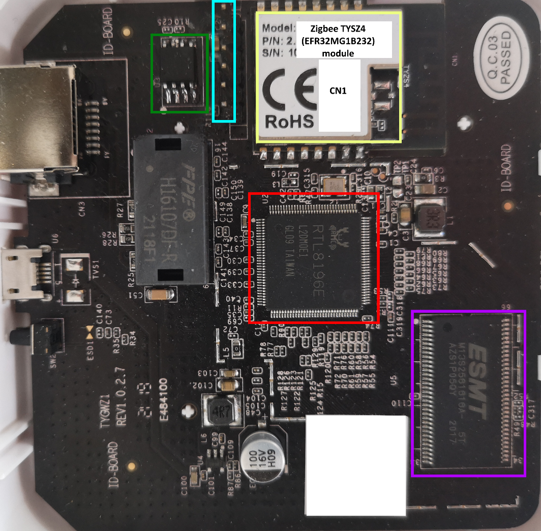
The other highlighted components are:
- red — RTL8196E main processor;
- green — 16 MiB SPI NOR flash;
- purple — 32 MiB SDRAM;
- yellow — TYZS4 module containing the EFR32 radio.
J1 pinout
Pin 1 is the bottom pin in the documented board orientation shown above.
| Pin | Signal | First-install use |
|---|---|---|
| 1 | 3.3 V VCC | Leave disconnected |
| 2 | Ground | UART adapter GND |
| 3 | RTL8196E serial TX | UART adapter RX |
| 4 | RTL8196E serial RX | UART adapter TX |
| 5 | EFR32 SWDIO | Do not connect for a normal install |
| 6 | EFR32 SWCLK | Do not connect for a normal install |
The three-wire serial connection is therefore:
Gateway J1 pin 2 GND  --------  adapter GND
Gateway J1 pin 3 TX   --------  adapter RX
Gateway J1 pin 4 RX   --------  adapter TX
Gateway normal power supply    (adapter VCC not connected)
TX and RX are intentionally crossed. The UART adapter is a signal interface, not the gateway power source.
RTL8196E serial console settings
| Setting | Value |
|---|---|
| Logic level | 3.3 V TTL |
| Speed | 38400 baud |
| Data format | 8 data bits, no parity, 1 stop bit (8N1) |
| Flow control | None |
Example with picocom:
Power on the gateway and press Esc repeatedly to stop at the <RealTek>
bootloader prompt. Serial text that is unreadable usually means the baud is
wrong; no text usually means the device, ground, TX/RX, or contact is wrong.
See Troubleshooting.
Main components
RTL8196E main processor (U2)
- Realtek RTL8196E with a 32-bit Lexra RLX4181 core
- 400 MHz CPU
- integrated Ethernet switch
- SPI controller for external NOR flash
- two 16550A-compatible UARTs at MMIO
0x18002000and0x18002100
The RTL8196E runs the custom bootloader and Linux. UART0 is the J1 console; UART1 connects to the EFR32 radio.
Datasheet: RTL8196E-CG.
SPI NOR flash (U3)
- GigaDevice GD25Q127C family
- 16 MiB capacity
- 64 KiB erase blocks
- stores bootloader, Linux kernel, read-only rootfs, and persistent userdata
Datasheet: GD25Q127C.
SDRAM (U5)
- 32 MiB SDRAM
- ESMT M13S2561616A or equivalent
TYZS4 radio module (CN1)
- Tuya TYZS4 module
- Silicon Labs EFR32MG1B232F256GM48
- ARM Cortex-M4 with IEEE 802.15.4 radio
- connected to RTL8196E UART1
- can run NCP, RCP, OT-RCP, or standalone Zigbee router firmware
Datasheets: TYZS4 and EFR32MG1.
Two debug functions, two use cases
J1 combines unrelated interfaces:
- Pins 2–4, UART0 — RTL8196E console. This is what a normal first Linux installation uses.
- Pins 1, 2, 5, 6, SWD — low-level EFR32 programming. This is required only for a virgin/corrupted EFR32 Stage-1 bootloader or specialist recovery.
Do not confuse the first-install UART connection with the internal UART1 link between the two chips. The user-facing serial console runs at 38400; EFR32 applications normally run at 115200 or faster on a different UART.